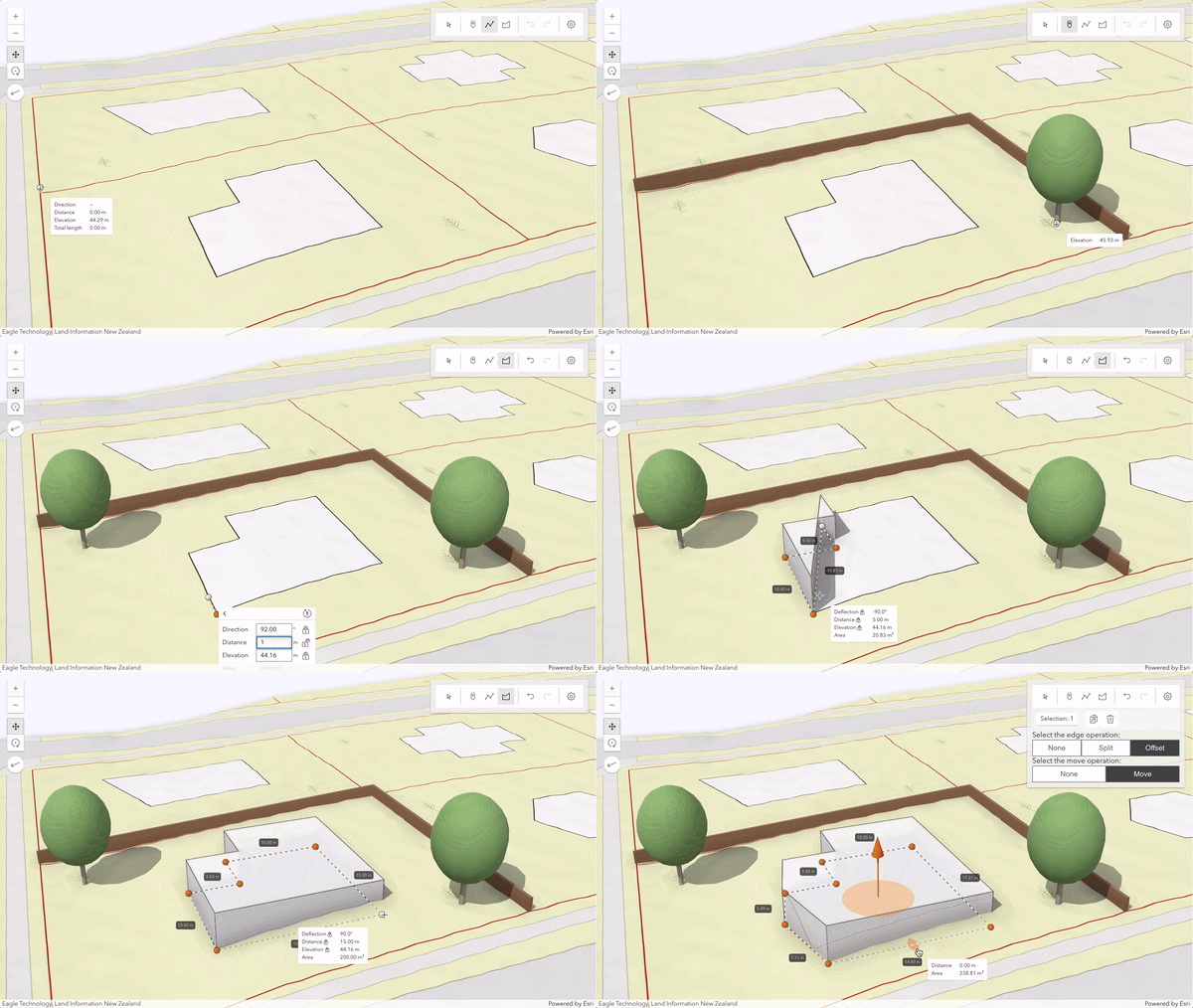
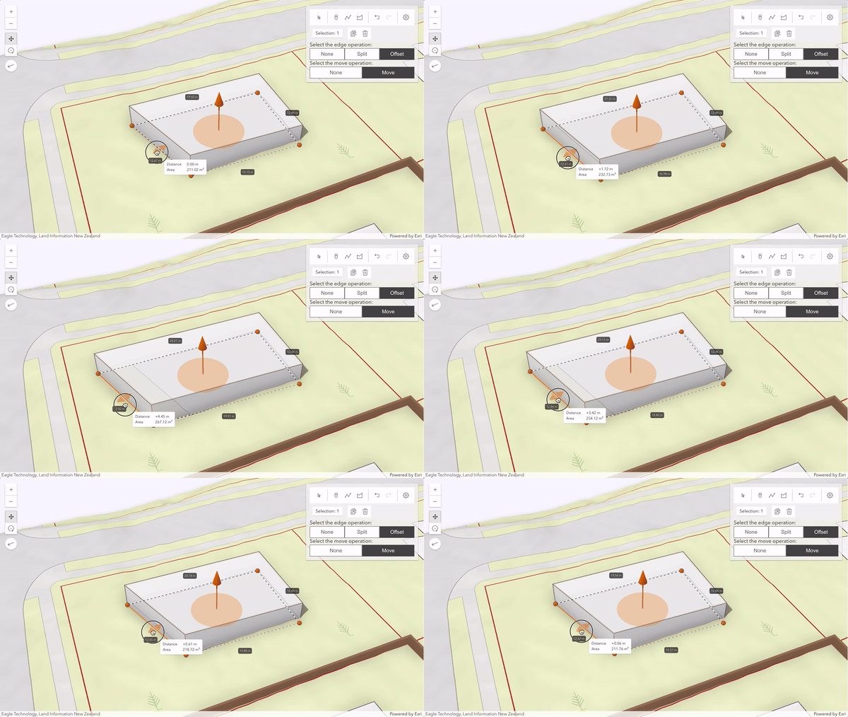
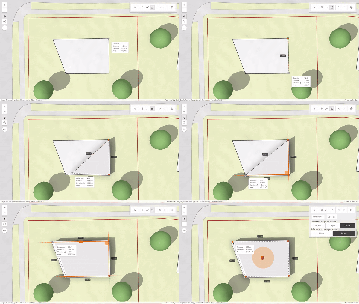
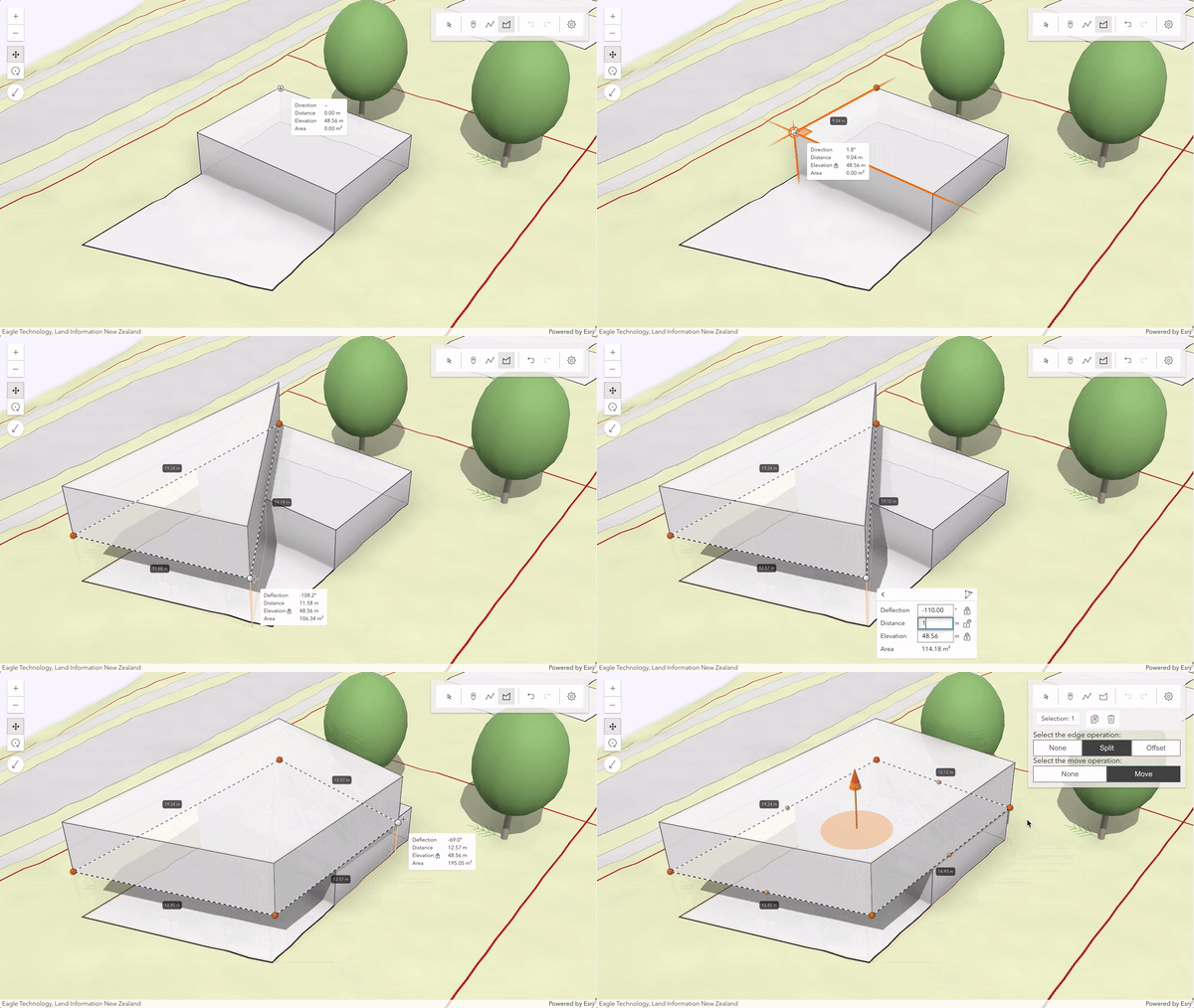
This sample demonstrates how to create graphics with 3D symbols and how to update these graphics using a customized Sketch widget in a SceneView.
Sketch widget
The Sketch widget provides an out-of-the-box user interface (UI) for creating and updating graphics. To use the Sketch widget, create a new instance of it and set its view and layer properties. The layer property allows to connect the widget to a GraphicsLayer which saves all the created graphics. In this sample, the widget is rendered inside an HTML element which ID is specified through the container property.
// Create the layer where the graphics are sketched and add it to the scene
const sketchLayer = new GraphicsLayer({
elevationInfo: {
mode: "absolute-height",
},
title: "Sketched geometries",
});
scene.add(sketchLayer);
// Create the Sketch widget and add it to the "sketchWidget" container inside the "sketchPanel" <div>
const sketch = new Sketch({
view,
container: "sketchWidget",
layer: sketchLayer
});
// Add the sketchPanel (which includes the sketchWidget <div>) to the view
view.ui.add("sketchPanel", "top-right");
Customization

The SketchViewModel provides access to the underlying logic of the Sketch widget, enabling customization of the behavior and the default geometries symbology. To do that, use the view property of the Sketch widget.
// To customize the widget furhter, access its underlying logic through the SketchViewModel
const sketchViewModel = sketch.viewModel;
This sample customizes the following options:
Default symbols per geometry type
One of the SketchViewModel's most powerful capabilities is the ability to customize the default symbols for each geometry by setting the point, polyline, and polygon properties.
// Customize the SketchViewModel symbols for each geometry type
sketchViewModel.pointSymbol = createSymbology("tree");
sketchViewModel.polylineSymbol = createSymbology("border");
sketchViewModel.polygonSymbol = createSymbology("building");
Update tool settings
With reshapeOptions, it is possible to modify the behavior of both the edge and move operations within the reshape tool for polygon and polyline geometries.
In this sample, the logic to toggle the reshape options is handled via a UI component that appears whenever Sketch calls the update() operation.
The following code snippet demonstrates how to configure the reshape manually.
// Define the default update behavior of the SketchViewModel
sketchViewModel.defaultUpdateOptions = {
tool: "reshape",
reshapeOptions: {
edgeOperation: "offset",
shapeOperation: "move",
},
};

Snapping
It is also possible to configure snapping within the Sketch widget. This is handled via the snappingOptions property. The Sketch widget provides a UI to toggle snapping.
// Customize the SketchViewModel snapping options
sketchViewModel.snappingOptions = {
enabled: true,
featureSources: [{ layer: sketchLayer }],
};

Tooltip and label options
The tooltip and label properties
provide helpful information when creating or updating features. You can enable them programmatically or toggle via the Sketch widget's UI.
Press Tab to activate the input mode while drawing a new feature or when editing a point, or selected vertex.
In the tooltips' input mode, one can set editing constraints or enter coordinates to achieve greater control over segment lengths, angles, as well as position and elevation values.
// Enable tooltips and labels on SketchViewModel
sketchViewModel.tooltipOptions = { enabled: true };
sketchViewModel.labelOptions = { enabled: true };

In this sample, when starting to draw a polygon or polyline, the tooltip shows the absolute direction mode (relative to the map's main axis, usually the north). But after the second vertex is drawn, the tooltip UI will switch to show relative direction (deflection) instead. You can set it via the valueOptions.
// When starting to draw, always show the absolute direction mode
if (event.state === "start") {
sketchViewModel.valueOptions.directionMode = "absolute";
}
// After the second vertex is drawn, change to relative direction mode (deflection)
if (event.state === "active" && event.toolEventInfo.type === "vertex-add" && event.toolEventInfo.vertices[0].vertexIndex === 1) {
sketchViewModel.valueOptions.directionMode = "relative";
}